This pages will still be hosted for your reference only, comments have been closed.
For further support, please join the new Facebook Walkera Scout X4 and Tali H500 Support Group and ask your questions there.
WARNING: Proceed with these mods at your own risk!!! These are not official Walkera suggested modifications and will likely void your warranty! If you bought from a reputable dealer please check with them first! If you bought directly from Walkera, good luck getting any response from them – or any warranty for that matter. Hopefully these mods will keep you flying, but I will not be held responsible for any damage or injury if you choose to proceed.
Some of these are currently necessary to stop you Scout from malfuntioning mid air and crashing!! These are hardware issues from the manufacturer – Walkera, you owe me a Scout!
Firstly, if you can’t solder, it’s time to learn or perhaps you shouldn’t own a Scout X4. When soldering, always heat the work area/wire first and let the heated wire melt the solder, not the iron – you will get a much better bond. Try not to heat the area up for too long or you may melt or destroy something it is connected to! – always leave a reasonable length of wire from a circuit board.
Time to take the lid off the Scout.
Protect and support your GPS antenna with foam Remove the battery and gimbal, turn Scout upside down.
There are two phillips head screws buried deep either side of the battery bay at the back. The rest (18) are 1.5M hex screws. The screws on the tips of each arm are smaller.
You don’t need to undo the motor covers on the bottom of each arm unless you want to check your motor screws or remove your motors.
You don’t need to undo the leg retract servo retainers to get the top of the Scout.
SERVO LEG FUSES:
An issue has been identified by Bo Loretzen that in certain instances of a leg retract servo failing an shorting, the motherboard can be damaged. If this happened mid air it can cause a crash! The solution is to insert a .5A fuse on the red wire running from the retracts to the bluetooth module as below:
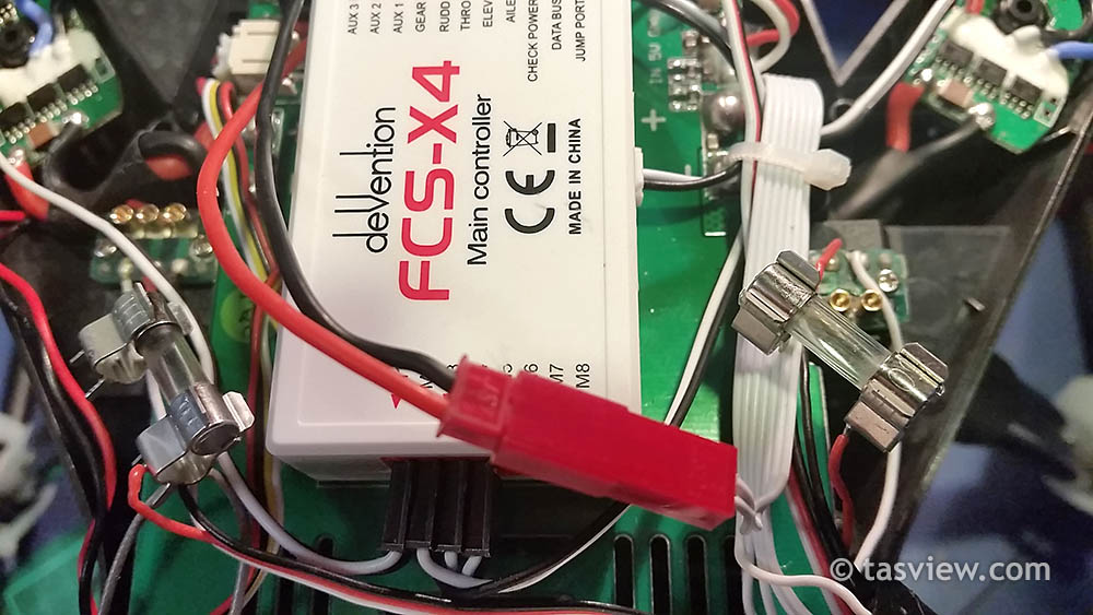
I couldn’t get pico fuses locally so I used these .5A quick blow glass tube fuses with holders soldered onto the red wire from the retracts – cover them fully with insulation tape or heat shrink.
These Pico fuses are smaller and lighter though with these fuse holders, or these PPTC resettable fuses recommended by Petri Junnila could be used.
LEG SERVO CUSHION MOD: Recommended and suggested by Matt Kim.
As can be see in the photo below, repeated use of the leg servo can cause a small switch inside to be pushed over by the brass riser which travels on the worm screw. This can not only cause the leg to stop retracting but can sometimes cause a short and take our your Scout’s mainboard too!! It is highly recomended to do the fuse mod above to save your mainboard as well as the following cushion mod to help prevent your retract from malfunctioning. You don’t need to pull the Scout body apart, just take off the legs and retracts.
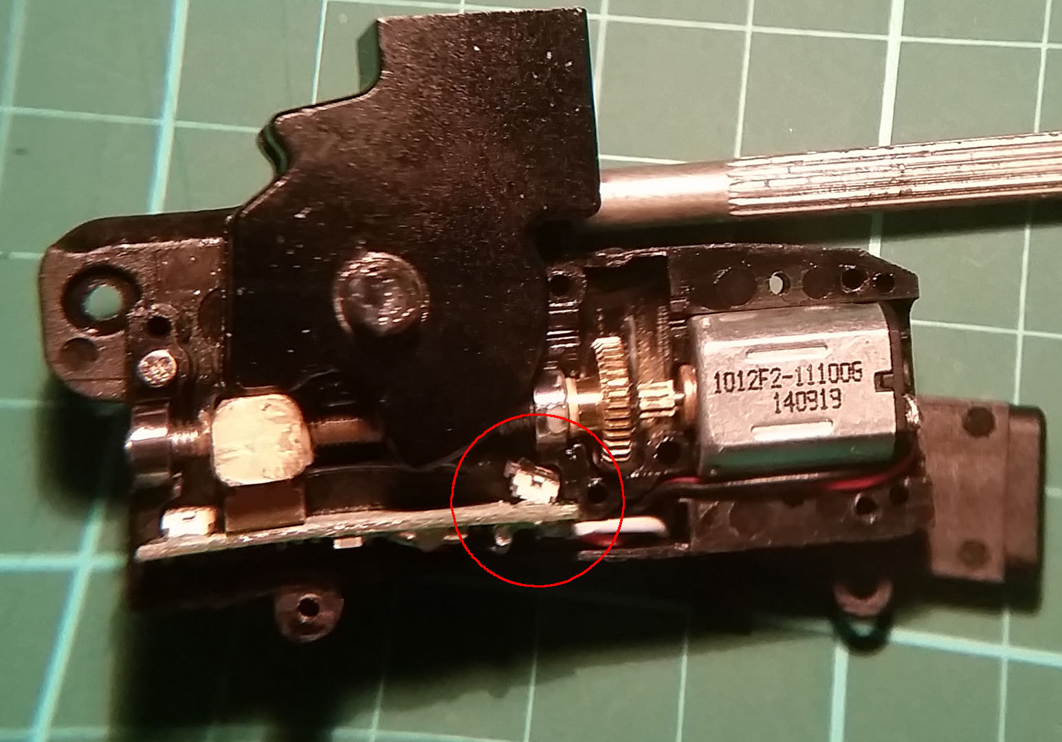
Parts are VERY small including the screws and easy to lose – do this over a bench, you may need a magnifying glass and tweezers, it’s fiddly but not difficult. SEE PHOTO BELOW: undo (top left) hex head screws on both sides – be careful not to lose the tube they support.
There are two larger screws on one side, these do not need to be undone. Undo the six small screws on the other side, the case will then split in half – be careful as things may fall out, don’t panic if they do, just don’t lose them.

Retract cushion mod below: Clean the block surfaces with alcohol first. Place 3m extreme mounting tape or adhesive soft cussion on both sides of the brass block to cushion the switches at either end.

Assembly is reversal of instructions – use the photo above as a guide for re-assembly. Pleas not, someone else who had done this mod still had their retracts fail, but it should extend their life. You should also install some fuses like above.
USB PORT MOD:
The Scout’s USB port is not attached to the PCB very will and has broken for several users. It is recommended to add some hot glue to strengthen as shown below. It’s fiddly and hard to get to. NOTE: You do not need to cut the wires as I have unless you want to add LED lights as shown further down – this is where I tapped into the 12V inside the Scout.

GIMBAL SENSOR MOD:
I took off the top gimbal controller and the tab at the back was no longer attached! Sorted it out with a bit of hot glue before it failed completely. I’d recommend this mod if you want your gimbal to last – it’s only 2 screws to undo. Matt Kim suggest leaving the screws slightly lose to give it some play.

LED LIGHTING MOD (optional):
Not necessary, but the lights pre-installed under each arm are very dim and useless in daylight so this will help with orientation at distances. There are quite a few variations of this in the Scout FB group, this is my take.
If using 5mm high vis LED’s you will need to solder a resistor to the positive (longer) leg to suit 12V as below.

Below shows my wiring, I added a switch and soldered it into the 12V wires shown in the USB port mod previously above. Make sure all wires are covered.

The end result:

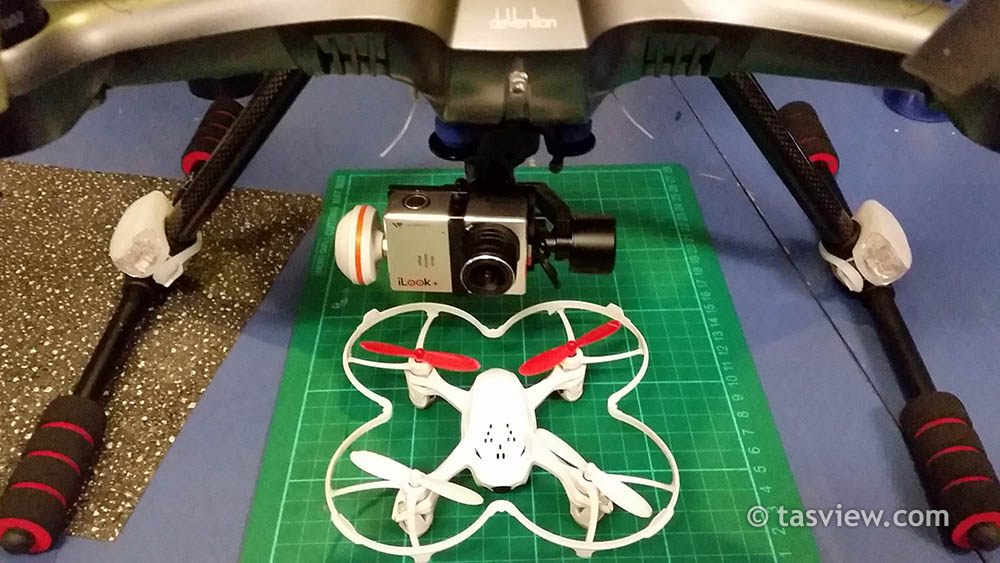
If your not comfortable with soldering, an easy and effective mod is to find some suitable lightweight bike LED’s and mount attached to the legs as shown below.
BT-2401B 2.4G BLUETOOTH DATALINK MOD:
The first time I plugged in my USB cable the port broke off and fell inside – Another first to find. Undo the 4 screws on the back and put some hotglue around the USB and UART ports.
You should also check the USB ports on the Devention Pad Holder – there are two USB’s and mine were not soldered on very securely so I put more hotglue on them.

BATTERY SWITCH MOD:
After balancing my Scout battery as normal for about the 30th time, the sliding switch started playing up. After some thought and discussion online, instead of replacing this main switch with another cheap slider, I replaced it with a mini toggle switch on to of the battery.
Remove the battery cover by gently levering off the tabs shown below, start at the bottom pulling outwards. There are two screws under the battery to remove, then seperate thetwo halves around the battery.

Mike unsoldered the old switch and soldered two wires on for me which are soldered to a mini switch. The pins need to be bent before soldering so it will fit not as shown below.

I put on some hotglue to insulate and strenghten the connections – there’s no need to be quite so generous 😉

For my switch a 6mm hole was drilled through the top of the battery cover, the switch poked through, the battery case with two screws and cover reassembled and more hot glue (I replaced this switch with a smaller mini-toggle switch).

Now hopefully it has a tail that keeps wagging 😉
F12E THROTTLE SPRING CENTREING MOD (optional):
Follow the instructions on page 11 of the Devo F12E manual to take apart the transmitter.

Remove Screw F, Screw G and remove the Throttle Control Spring. Remove the Linkage Fixed Screw (on side) from the throttle.
Tension can be adjusted using the screw facing you near the Linkage Fixed Screw location.
Re-assemble your transmitter, your throttle will now have a centre spring. Remember, you will need to hold it in the 0% throttle bottom position when binding.
ANTENNA MODS (optional): (Section to be updated as I learn)
2.4GHz FOR CONTROLS: One of the easiest mods is to purchase a 2.4GHz 8dBi Omni-Directional Antenna like the TP-Link TL-ANT2408C and a SMA Male Plug To RP-SMA Female Plug RF Coaxial Adapter Connector (the adaptor has two male ends) to replace the supplied 2.4GHz antenna on the F12E controller. This will increase the controller range/distance. For best results it should be kept side on to the craft, not pointed directly at it.
5.8GHz FOR VIDEO: The default antennas for video have a limited range of around 300m. I am currently researching options to replace these antennas.
I’ve ordered the following parts for a GoPro3 setup – I will update my findings after intallation. The parts selected are budget items, there are better out there like the ibCrazy bluebeam sets but for me this is more about increasing the safety margin rather than how far away I can fly.
Boscam FPV 5.8G 200mW AV Wireless Transmitter TS351
5.8G 3 Leaves Omnidirectional Gain Antenna For Transmitter
5.8G 4 Leaves Omnidirectional Gain Antenna For Receiver
The transmitting and recieving cloverleaf antennas need to be positioned side on for best transmitting range, not pointed at each other.
Here is some information from my notes on antenna options:
RX antenna to fly more than 1km on DevoF12E. http://fpvlr.com/shop/index.php?route=product%2Fproduct…
Fatshark goggles on the Scout – default is ch8
https://www.youtube.com/watch?v=kebwin6fi84
TX5804 transmitter Use the two cable in the spare parts bag. One goes to the gopro the other from the 5803 to the Scout 12v
Making the Best RF Shield for the GoPro Hero3 + https://www.youtube.com/watch?v=f4OZYsdSnB8
I have ordered these:
MinimOSD MAVLink OSD APM 2.6 APM 2.52 Flight Control Board40pcs 20cm Male to Female Jumper Cable For Arduino
Dont forget to check out the SCOUT X4 GETTING STARTED GUIDE and the MISSION PLANNER SETTINGS PAGE for further recommended changes and tips!
*If you appreciate the time, effort and research gone into this website or if you feel it’s helped you avoid a crash, please give tasview.com a mention in groups and forums or help us answer questions in the comments below 🙂
Thanks for visiting.
______________________________________
This pages will still be hosted for your reference only, comments have been closed.
For further support, please join the new Facebook Walkera Scout X4 and Tali H500 Support Group and ask your questions there.

AWESOME!!!!!!!!!!!!! thanks for all the help and support figuring this out
LikeLiked by 1 person
Hey, thanks for all the useful tips.
The issue I’m having with my Scout is, Whenever I put it in GPS hold (MIX SW “1” )
My scout stays in place and does slow clockwise rotation and I lose functionality of the ail/elev stick. Do you have any idea of what might be causing an a solution to the problem….Please Help….thanks
LikeLike
I could be wrong, but it sounds like it’s putting it into Circle Mode instead of GPS. Normally Circle mode is switching the FMOD switch to 2 position. Sounds like your switches are programmed wrong.
LikeLike
were any of the mods taken care of from the walkera on newer models I wonder. also when u are talking about ground station use mission planner etc and u say not yet working etc i was wondering if that is still the case I am always looking for dates to see if it is still current or if it was an old post. Not that it matters I haven’t yet not from lack of trying been able to set up ground station mission planner etc anyway I’m so confused it isn’t even funny!! research every day trying to find a way and furthermore gcs app is what they say in the book and can’t evan get that on google play more less iOS. reading your stuff has fought me more in one night than everything I have learned in the last 4 nights since I got my scout. thanks so much!!!!!!!!!!!!!!!!!!!!!!!! maybe when u have time u can do a detailed guide for hooking up to mission planner or gcs or amp witchever it is we are suppose to be using since the guide gives us terrible directions on something that doesn’t exist anyway!!!(GCS app)
LikeLike
I’m sure I will learn and Im sure it is covered somewhere just haven’t found it all yet lol hope it don’t fly away before I learn this stuff lol!!
LikeLike
curious if your led light mod has any effect on camera and could u post a pic of front view with lights off hard to see. looks real cool lit up thanks
LikeLike
The lights have noticable effect on image quality. The bike lights on the legs are easier to see and adjust compared to the strip LED’s I installed. You could also put them on the front arms instead of the legs – buy light weight ones though.
LikeLike
Myself and Tone fly together (I run a Phantom Vision 2 Plus (Ver. 3.0) and I must congratulate Tone on doing an enormous amount of work to assist with the X-4 for others who fly them. Well done Tone, you are a credit to the UAV community.
Mike
(TASVIEW)
LikeLiked by 1 person
Hey from Amity Oregon, just got my Scout ,jumped up from a Blade 350, WOW what a major ass pain. I wish i found your forum before i bought this Chinese Jigsaw Puzzle. WTF? I have been reading for 2 weeks before i attempted my first flight it went 3 feet up, hovered for a moment and it did not land hard but i heard a distinct snap. The landing skid broke. I put packing tape on it and tried again. This time i got 3 of the 4 motors working. God knows why they were not all working, but wait i tried again and yes now we have 2 of the 4 functioning as intended, the other 2 motors were probably sleeping, not sure how to awake them? Anyway i appreciate your article.
LikeLike
Hello to Amity Oregon,
Interesting experience, I’m Mike the Phantom 2 Vision Plus owner Pilot Administrator on this forum, but I would very much like to hear Tones take on some motors starting, and others not – I have to ask this, how is this even possible, my question is how can this possibly be pilot error (question to Tone) – I mean no matter what mistakes you make, some motors starting and some not cannot possibly be attributed to the pilot doing anything? Do I make sense here. Once again I am not the Scout owner. Advisor here, I have been a mere witness to Tone’s issues – as we fly together.
Happy Flying, and yes – Tone is a tremendous credit to the X-4 community with his sharing of experiences and knowledge.
Phantom 2 Vision Plus Pilot
Mike.
LikeLike
Hi Brian, it’s probably best to test your motors on a bench with the props off to make sure they are working properly. If they all work but are firing up uneven, apparently that’s “normal”. When you take off in “manual” mode, increase the throttle to around 30% and wait until all motors are spinning nicely before moving your throttle quickly to around 70% and launching quickly to around 2m – follow the full takeoff routine on the getting started page.
If motors aren’t firing up until over 30-35% or not at all, there may be another issue. Some users have reported crushed wiring inside their Scout. If you can’t return yours for some reason and your comfortable fiddling with electronics, you may have to lift the lid and have a look. You may have pinched a wire during your hard landing. I wish you luck Brian – you’ll probably need it.
LikeLike
Great info here. Really like this site. Question? I do have the Scout X4 with the G-3D Gimbal/ilook+. I had a poor landing one day and now notice that the camera is no longer fixed to the center of the X4. Everything looks normal and the pitch and roll are functioning correctly. The gimbal appears to be ok. Is there a way to adjust the motors to make the camera align center. Please help.
LikeLike
Good question, my gimbal has been bent more than once and although I’ve managed to rebalance it, it points to the right. I’m pretty sure theres a trim setting on the F12E that may correct this but I have yet to look into it, been a bit busy of late. If i find out I’ll let you know, if you beat me too it, please share 🙂
LikeLike
I had a look through the radio this morning but could only find adjustment for tilt and horizon but not pan centering. I very gently – using two pairs of plyers covered in cloth – bent my gimbal back around to where it should be and it now points straight again. The metal used in the gimbal arms seems to be quite soft and not brittle, but please be very careful if you try it – and don’t blame me if you break it (read our disclaimer page). Try not to put any pressure on the motors when doing this.
LikeLiked by 1 person
I had a real hard landing, pretty much landed on the right landing arm and crushing the iLook+ & gimbal. My camera was scrap metal & gimbal was wayyy off center. … After ordering a new iLook+, I powered off gimbal, centered it as much as i could. Placed the new iLook+ on there, power on, and manually centered the gimbal (i could hear the motors trying to center the camera) . Its now strait and fully working 100%, i just saved myself $90 bucks on a new gimbal… Hope my info can help.
LikeLiked by 1 person
I took both pieces of advice and now my gimbal is centered. It worked! Thanks for the advice. Saved me money and made me a friend 🙂
LikeLiked by 1 person
Thanks for the feedback, glad you got it sorted. Cheers 🙂
LikeLike
LikeLiked by 1 person
Thanks for the head’s up – a great tip! Added to the Setup page 🙂
LikeLike
Hey everyone….awesome site!
OK so I have successfully run through some automated landing, altitude hold and automated landing using g the GCS app. The major reason I got this thought was their claim to the Fallow Me mode. Well I have tested that and the problem is while in fallow me it does this significant twitch or hiccup in its flying. Enough that it will ruin the shot. Seems to me like this is a software based issue. Has anyone e had a different experience with this?
LikeLike
Hello,
Thanks for the informative posts, the pictures really help.
I have completed the landing gear limit switch padding mod, and the landing gear fuses.
I am looking for a reliable 5v connection within the body to connect my GoPro and some LED lights, and am having a bit of trouble locating one.
Is there a good place to tap into to get 5v, or do I need to install a voltage converter?
Thanks in advance!
David
LikeLike
I just found this info for you, not sure if it is correct so please check voltage!
“You can use the 5v, ground and signal wires from FC to bluetooth data module. The problem where i struggled alot is that the wires are not properly color coded. Black is signal you need to use to minimosd, the red is ground and one of the other’s (forgot) is 5v.”
LikeLike
Hi to all..
I received my Walkera scout x4 today and started doing some of the mods that are posted here. When taking out the connections from the controller, I forgot to mark the connectors that was plug to the GPS and compass port. Can you please tell me which one goes to the Compass port and which one goes to the GPS port? Thanks..
LikeLiked by 1 person
White goes in telemetry and the black and red cable on compass. Blue black and red one in gps.
LikeLike